SWARM-EX, Space Weather Atmospheric Reconfigurable Multiscale Experiment, is a large project sponsored by the National Science Foundation. Six Universities in total are working on this project. They include: Georgia Tech, Olin College, Stanford University, University of South Alabama, and Western Michigan University.
Craft Overview:
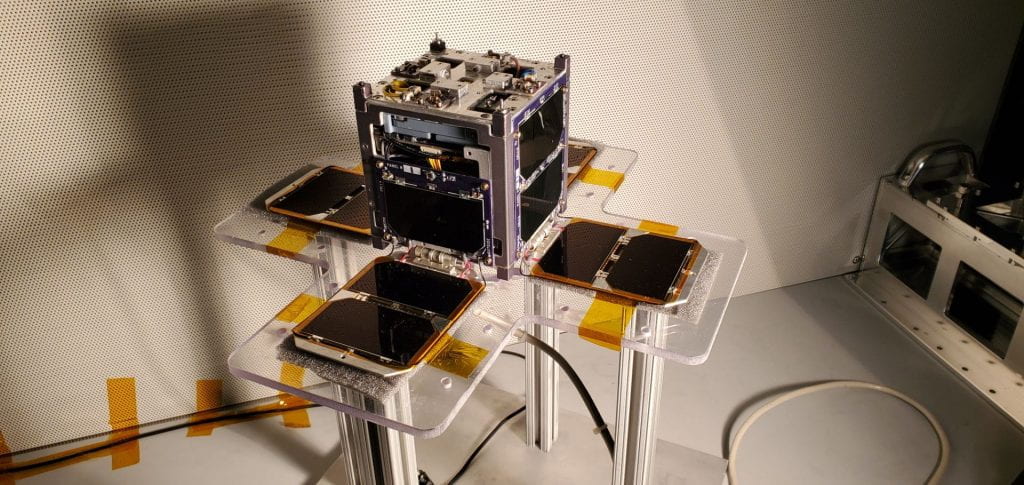
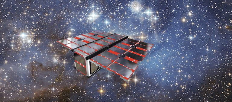
SWARM-EX’s purpose is to explore the relationship between charged and neutral particles in the thermosphere. This region of the atmosphere is about 90 km above the Earth’s surface. The cubesat will explore the Equatorial Ionization Anomaly as well as the Equatorial Thermosphere Anomaly. This project began on January 1, 2020 and is expected to be completed after four years.
Sources and Additional Information:
- https://ssdl.gatech.edu/research/projects/swarm-ex-space-weather-atmospheric-reconfigurable-multiscale-experiment
- https://ae.gatech.edu/news/2019/11/lightsey-and-colorado-colleagues-get-nsf-grant-study-earths-atmosphere
- https://www.colorado.edu/aerospace/2019/10/16/building-satellite-swarm-investigate-atmospheric-anomaly
| Acronym | SWARM-EX |
| Full Name | Space Weather Atmospheric Reconfigurable Multiscale Experiment |
| Size | 3U |
| Status | In Progress |
| Launch Date | TBD |
| Principal Investigator | Glenn Lightsey |